Article of the Month -
may 2004
|
Direct Geo-Referencing in Practical Applications
Dr.-Ing. Ralf Schroth, Vice President of FIG
This paper was for
the first time presented at the ISPRS workshop WG 1/5 about Theory,
Technology and Realities of Inertial/GPS Sensor Orientation in
Castelldefels/Barcelona, Spain, 23 September 2004. It has been partly
revised for the FIG Article of the Month published in May 2004
 This article in PDF-format.
SUMMARY
This paper gives an overview to modern technologies in GPS/INS for direct
geo referencing from the application point of view. It also describes the
integration of these new technologies into mapping market and for other use
of surveyors. Empirical results from more than 30 projects are discussed.
1. INTRODUCTION
In the field of photogrammetry and remote sensing airborne sensors are
more and more applicable. This can be seen directly in relation to the
establishment of Geographical Information Systems (GIS) in most of the
geospatial applications. The users are requiring fast, inexpensive and
actual information. The most common airborne sensors nowadays are still the
optical systems (passive) like film cameras. But also the different sensors
for multispectral applications. Additionally active sensors like the
airborne laser systems (LiDAR = Light Detection And Ranging) or InSAR
(Interferometric Synthetic Aperture Radar) are more and more important.
Especially LiDAR mapping is a fully accepted technology to generate high
accurate digital terrain models (DTM). For all these sensors it is necessary
to know their 3-dimensional orientation during the time of detection of the
information. This is known in photogrammetry as the determination of the
exterior orientation parameters and is a standard procedure called aerial
triangulation in the photogrammetric workflow.
Since in the seventies additional sensors like the statoscope [1] and
later on the application of differential GPS were introduced to measure the
elements of the sensor orientation in a direct way. The aim was always to
reduce the necessary number of ground control points [2]. Only in the last
few years the direct measurement of all parameters of the exterior
orientation (so called direct geo-referencing) by a combination of GPS and
INertial System (INS) or Inertial Measurement Unit (IMU) was successful and
could be offered at a reasonable price to the users.
In the following some of the typical sensor systems in practical use
should be introduced. The latest results of several projects and sensor
types will be presented and the experiences out of the projects from the
point of view of a service company will be described.
2 SENSORS AT AN AERIAL SURVEY COMPANY
The most common sensor in the field of surveying and mapping is still the
traditional aerial film camera. It is assumed that there are about 1,000
systems worldwide available whereof about 500 cameras are in daily use (see
figure 1). The typical applications are the exposures of black and white,
color and color infrared images, which are used for photogrammetric mapping
and interpretation. The aim of the integration of IMU’s is to reduce or
avoid ground control points and the production step of aerial triangulation.
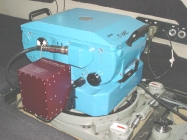
Fig. 1. Photogrammetric film camera RMK TOP (Z/I Imaging) with IMU
Aerocontrol (IGI)
The latest developments are to replace the film cameras by optical
digital sensors of similar ground coverage. All of them offer or
respectively need the INS for their orientation. A “small format” version
can be seen in figure 2; this system has an integrated INS of APPLANIX. Some
test flights and the first commercial project showed very reasonable results
for special applications (see chapter 4).
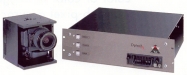
Fig. 2. Digital camera ALTM 4K02 with control unit (Optech)
Besides the optical sensors for mapping applications like photogrammetric
stereo plotting or digital orthophotos the LiDAR systems are since their
strong development during the last 12 years in daily operations. These
systems can only be directly geo-referenced and need therefore the GPS/INS
system which is an integrated part of it. An example can be seen in figure
3.
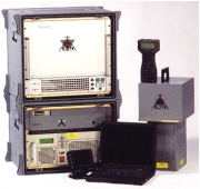
Fig. 3. Airborne laser scanner type ALTM 2050 (Optech)
Among all the different multispectral systems the thermal scanning (see
figure 4) devices are used quite often for the observation and control of
temperatures of different features on ground like rivers, leakage of heat
pipes etc. As the system needs to be referenced to a ground coordinate
system also the GPS/INS to get the orientations of the scan lines in an easy
and fast way.
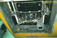
Fig. 4. Thermal scanner in Cessna 402
3 DIRECT GEO-REFERENCING – THE SYSTEM
The method of direct geo-referencing allows to transfer sensor or object
data immediately into a local or global coordinate system, which makes their
further processing possible (see figure 5). Such a system exists of
receivers of the global positioning system (GPS) on board and on the ground
(reference stations) and an inertial system combined with a sensor, which
determines angles and accelerations of the sensor with high precision (see
figure 6).
The components of the complete system could be:
- Inertial system (INS)
- 12 channel L1/L2 GPS receiver
- Controller
- Flight management system
- GPS reference station
|
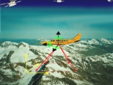
Fig. 5. Principle of direct geo-referencing positioning (X,Y,Z)
and rotations (phi, omega, kappa) will be captured during the survey
flight |
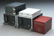
Fig. 6. GPS/INS system Aerocontrol (IGI Kreuztal) as an example. |
4 DIRECT GEO-REFERENCING – THE APPLICATIONS
4.1 Projects
There is now some years experience in photogrammetric companies with the
method of direct geo-referencing with GPS/INS systems. LiDAR systems were
used since more than 10 years very successfully with integrated GPS/INS
systems. The GPS receiver and the INS form together with the laser system a
compact unit. By the use of several calibration procedures the results of
the LiDAR survey have an accuracy of up to 15 centimeters.
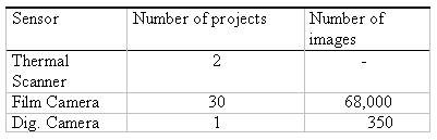
As an example the company Hansa Luftbild is operating since about three
years the modular system Aerocontrol for the combination with several
sensors. First results were presented in 2001 [3]. In total more than 30
projects were finished now (besides the LiDAR projects which will be far
more than 100). In table 1 the used sensor types are shown.
The main focus is on the analog film camera with about 68,000
images taken in combination with the GPS/INS system. Thereof for about
40,000 images the GPS/INS information was used for tests and safety reasons
under special terrain conditions. Some of these tests resulted in a
long-term study of system calibration (see [4]).
For about 20,000 images the parameters of the exterior orientation were
determined and delivered to the clients for their internal use. No
information about the quality of these data is available neither their use.
Tests were done by the customers themselves. Only about 8,000 images were
used in house for further production processing under the control of the
quality management system.
Table 1. Summary of GPS/INS related projects.
All the internal production resulted in the generation of digital
orthoimages. The DTM data was delivered by the clients or bought by the
regional surveying authorities. The DTM quality and resolution was chosen in
respect to the ground resolution of the orthoimages. The quality of the
orthoimages was verified by joining images, digital maps and ground control
points. In many cases the existing DTM was not sufficient and had to be
corrected or filled up with higher resolution DTM data.
So for about 60% of these projects the parameters of the exterior
orientation determined out of the IMU data were completely sufficient. For
the remaining 40% of the projects additional efforts were necessary. The
quality control showed differences which could not be explained by the DTM,
standard calibration procedures or similar effects. Therefore these projects
were determined by the help of the traditional aerial triangulation. In some
cases the overlap of the images was only 30% which is sufficient for direct
geo-referencing but not for the aerial triangulation method. The computation
of the old procedure called “Anblock” where only the overlapping areas were
used for a horizontal triangulation step like in the former model block
adjustment brought very reasonable results. This means that some of the
defects of the direct geo-referencing were caused by remaining tilts
(heading) of the images which could be caused by remaining systematic
errors. Of course in a production environment it was impossible to analyze
the exact reasons for these defects.
The projects with the thermal scanning device in combination with
the Aerocontrol system were quite successful. The GSD was 1,5 m, flying
height 750 m above ground. An example of the geo-referenced thermal data can
be seen in figure 7.
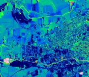
Fig. 7. Thermal image (direct geo- referenced by Aerocontrol)
The latest experiences this company had with the digital camera system
ALTM 4K02 in combination with a LiDAR system. The aim was to produce a
digital surface model by LiDAR data and a digital orthoimage out of the
camera data. This project showed similar effects as we have seen with the
classical film camera. To get reasonable results the system calibration has
to be done carefully. The GSD was 0,15 m and the maximum differences at
joining images were 0,50 m. The further improvement of the calibration
procedure promises even better results.
4.2 Lessons Learnt
The experiences with the direct geo-referencing are quite interesting. It
was found out in the beginning that for the determination of the
misalignment a separate calibration field in the vicinity of the airport,
where the planes are located, is insufficient to take the systematic errors
optimal into consideration. The calibration fields are now located inside
the area to be flown and must be flown at the same flying height as the
whole project. To get the best accuracy this calibration will be done for
each flight day and depending on the total length of the daily mission at
the beginning and at the end of it. For safety reasons it is recommended to
have a forward overlap of the images of 60% to determine if necessary an
aerial triangulation.
Besides these points there are some useful regulations during the survey
flight itself which have to be taken care of by the flight crew. The
long-term stability of the INS has to be taken into account for example when
long strips have to be flown.
As the direct geo-referencing method is working without any ground
control the datum transformation is also quite sensible. All the information
of the sensor is referred to WGS84 system. The final results normally are to
be delivered in a local coordinate system, which has certain network
deficiencies. As the transformation parameters very often are only available
for larger areas with a certain approximation identical points in the
vicinity of the area to be flown are necessary.
The integration of the GPS/INS data into the aerial triangulation is also
often discussed. Specially to get better approximation values for the
automatic procedures. In practical applications we have seen that the GPS
data are completely sufficient as start values for the triangulation
process. So an additional use of the INS system is a matter of economics. It
has to be analyzed if the number of the ground control points can be reduced
further more in comparison with the standard use of differential GPS. But
also in this case the decision will be taken by economic aspects, i.e. the
costs of ground control points vs. the INS. An overall technical discussion
of this topic can be seen in [5].
The direct geo-referencing of the sensor data has from the application
point of view still a lack of reliability. Many quality control procedures
are necessary. The refinement of the mathematical model by many years of
research and empirical tests and the high redundancy and reliability of the
indirect method like the aerial triangulation ended in a very comfortable
environment for the user and above all in a fully acceptance by our
customers. To get the same situation with the direct method some more of
independent experiments and qualified prediction procedures are absolutely
necessary.
5 CONCLUSIONS
The use of GPS/INS for direct geo-referencing of airborne scanning
devices is nowadays standard. Without this new technology their application
would be nearly impossible. Most of the actual developments of digital
optical cameras offering integrated IMU’s.
For conventional analog aerial images the procedure of the aerial
triangulation is still preferred in the case of stereo plotting. But for the
generation of orthoimages the method of direct geo-referencing is coming
more and more in practical use. Questions of redundancy respectively
reliability, prediction of accuracies and quality control are still open and
have to be solved. The procedures for system calibration and determination
of the exterior orientation are quite sophisticated and need very skilled
engineers.
It is out of question that the application of IMU’s are of great
advantage in low-contrast areas like lakes, coastal or dessert zones. The
final decision of the use of IMU is besides these technical aspects strongly
be influenced by the economical aspects and will be taken project wise.
REFERENCES
- Ackermann, F.: Accuracy of Statoscope Data – Results from the
OEEPE-Test “Oberschwaben”. Proceedings of ISP Comm. III Symposium, DGK
Series B, No. 214 (1974), 280-286
- Friess, P.: Kinematische Positionsbestimmung für die Aerotriangulation
mit dem NAVSTAR Global Positioning System. DGK Series C, No. 359 (1990)
- Schroth, R. (ed.): Hansa Luftbild Symposium on High Precision Sensor
Orientation – On the Way to Direct Geo-Referencing. Münster (2001)
- Cramer, M. and Stallmann, D.: System Calibration for Direct
Geo-Referencing. Proceedings of ISPRS Comm. III Symposium, Graz (2002)
- Cramer, M.: Integrated GPS/inertial and digital aerial triangulation –
recent test results. Proceedings of Photogrammetric Week, Stuttgart (2003)
CONTACTS
Dr.-Ing. Ralf Schroth, Vice President of FIG
Hansa Luftbild Sensorik und Photogrammetrie GmbH
Elbestr. 5
48145 Münster
GERMANY
Email: schroth@hansaluftbild.de
Web site: http://www.hansaluftbild.de
 |


