Indoor Parking Facilities
Management Based on RFID CoO Positioning in Combination with Wi–Fi and
UWB
|
Vassilis GIKAS. Greece |
Harris PERAKIS, Greece |
Allison KEALY,
Australia |
Günther
RETSCHER,
Austria |
Thanassis MPIMIS,
Greece |
Constantinos ANTONIOU,
Germany |
1)
This paper is a peer review paper that was presented at the FIG Working
Week 2017. Fixed geometric constraints, imposed by man-made structures,
weather influences, etc., make it possible to restrict positioning. In
this study, these problems will be subjected to a number of tests and a
low-cost solution will be offered.
SUMMARY
The advantage for the development of a positioning solution for
indoor parking facilities management relates to the fixed geometric
constraints imposed by man–made structures, the minimal weather
influences and the low vehicle dynamics. Furthermore, easy access to
commodities such as electrical supply and internet can facilitate
further the use of alternative localization procedures.
Nevertheless, other factors, including the severe multipath conditions
and the high attenuation and signal scattering effects, as well as the
extended non–line–of–sight (NLoS) conditions make the positioning
problem a difficult and case dependent task. This study offers a
low–cost positioning solution to the problem relying primarily on the
RFID Cell of Origin (CoO) technique resulting into a discrete point
vehicle trajectory. Then, Wi–Fi Receiver Signal Strength (RSSI)
observations act as a supplement to fill in the gaps and refine in a
dynamic manner the final continuous vehicle trajectory. Also, this
study introduces the concept of using UWB technology as a means of
supporting the RFID/Wi–Fi solution through dedicated check points of
higher positioning accuracy given its high accuracy potential and the
continuously decreasing system cost. A number of tests have been
undertaken to examine the validity and the potential of this approach
and results of the analyses are presented. It could be proven that
all major user requirements (i.e., positioning accuracy, availability,
continuity) are being met.
1. INTRODUCTION
Positioning requirements for indoor localization can vary extensively
depending on application type and scope of a particular study.
Therefore, the selection of the appropriate positioning techniques and
the allocation of suitable technologies to address the problem
necessitates a thorough designation of well–grounded figures of user
requirement parameters. For the case of traffic modelling studies
within large–scale, multi–storey indoor parking facilities and depots,
positioning requirements range from very loose to more stringent ones,
as the level of detail in simulation increases from macroscopic to
mesoscopic and microscopic scale respectively (Kladeftiras and Antoniou
2013, Antoniou et al. 2011).
This study deals with the positioning problem associated with the
traffic modeling concerning the management of indoor parking garages at
a microscopic level. As a result, the extraction of vehicle
trajectories and the measurement of their kinematics becomes crucial for
the calibration of the underlying transportation models. Previous
studies have employed various technologies to address the localization
problem within indoor parking facilities. Certain solutions
comprise the use of LD–LRS lasers (Kümmerle et al., 2009),
environment–embedded LIDAR sensors (Ibisch et al., 2013) as well as
Ultra Wide Band (UWB) systems (Baum, 2011). However, more
recently, low–cost approaches become more popular. For instance,
Bojja (2013) proposes the use of a gyroscope and an odometer sensor
system interacting with a 3D map database, while the approaches proposed
by Alam et al. (2015), Shuaib et al. (2015) and WLAN Positioning
Technology (2014) rely on WLAN measurements.
The authors, in a number of recent studies (Gikas and Retscher 2015;
Gikas et al., 2015; Gikas et al., 2016a; Antoniou et al., 2017) have
proposed and tested a positioning system that primarily relies on the
RFID (Radio Frequency Identification) proximity detection technique
aided by Wi–Fi monitoring. In this approach, the RFID is used to
provide a core solution for vehicle positioning, while the Wi–Fi acts in
parallel for verifying this localization solution and potentially
filling the gaps where necessary.
In this study, we propose an extension to this method aiming at
further improvement of the vehicle navigation solution, particularly in
terms of availability and coverage. To this effect, we utilize the
RFID–derived vehicle trajectories to compute Wi–Fi radio maps in the
area of operation using the empirical fingerprinting technique.
These maps are updated dynamically when an RFID solution is available,
while in the case of RFID outages they are used to serve vehicle
localization, leading overly to a more robust positioning solution.
Finally, additional considerations aiming at further improvement of the
method are discussed. These are based on the concept of DWi–Fi
(Retscher and Tatschl, 2016a; Retscher and Tatschl, 2016b) and the use
of the UWB technology respectively.
2. LOCALIZATION NEEDS FOR INDOOR
PARKING FACILITIES MANAGEMENT UNDER CONSTRAINTS
As already stated, this research aims at serving the localization
needs associated with the calibration of the transportation models
concerning the management of large–scale, indoor parking facilities.
Particularly, the interest focuses in cases of near–capacity demands,
temporally constrained arrivals / departures and for emergency
evacuation. In fact, the microscopic scale of the analysis adopted
in this approach, calls for an adaptive vehicle localization scheme
based on space–signal behavior. This should encompass analyzing
the performance of the localization and data processing methods in terms
of performance and complexity trade–off and shall also include
development of intelligent algorithms / software for the optimal use of
different positioning methods to ensure localization in complex
environments.
Four types of user requirements one should consider for the
development of an indoor localization system; namely, positioning,
interface, cost as well as security and legal requirements.
Particularly, positioning requirements comprise of several parameters
including accuracy, availability, integrity, coverage and continuity.
In the problem encountered in this study, despite the great importance
of positioning accuracy, other parameters, particularly position
solution availability, coverage and continuity are of vital importance
to the calibration and verification of the transportation algorithms.
Vehicle positioning accuracy, generally is required in the level of a
meter or so, while the direction of movement is also important to
compute in real–time. Finally, vehicle topology (i.e., spatial
distribution of vehicles) in a parking facility and its variation with
time provides useful information to control traffic modeling algorithms.
3. LOCALIZATION PRINCIPLES AND
TECHNIQUES
Position fixing indoors can be accomplished using various techniques
depending on the type of measurements and the environmental conditions.
The most common ones are the Cell–of–Origin (CoO) or proximity
detection, lateration, fingerprinting, dead–reckoning, and map–matching.
Here, the emphasis is placed on the first three techniques as they suit
better to the sensor technologies adopted in this study.
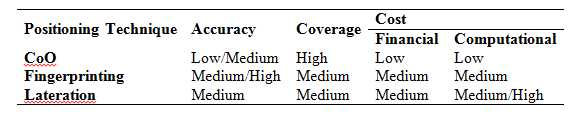
Table 1: Characteristics of the CoO, empirical
fingerprinting and lateration techniques. The CoO technique is
used to determine the position of a mobile asset within its range of
operation through identifying the location of the anchor point (e.g.,
RFID reader, Wi–Fi access point (AP)) which exhibits maximum RSSI
(Receiver Signal Strength) value. Notwithstanding the CoO
technique is very simplistic at an implementation stage, its accuracy
standard is low compared to other techniques (Table 1). Location
fingerprinting (FP) relies on RSSI maps constructed at a training phase
to depict the distribution of RSSI at an area of interest. At a
second stage the measured RSSI values are cross–compared against the
reference ones that implicitly correspond to a position fix. FP
generally provides a medium to high accuracy standard, nevertheless the
training phase can be time consuming and costly. Finally, the use
of the lateration technique resides on computed (in the considered case
from RSSI measurements) ranges that connect the unknown location of a
user to control points fixed at known locations. The level of
accuracy of the method is mainly affected by multipath due to obstacles
in the environment that contaminate the RSSI measurements.
4. POSITIONING USING RFID AND Wi–Fi
An RFID is a radio frequency (RF) system that can be used for object
and pedestrian detection, positioning and tracking. It employs a
reader operating in the frequency band from 300 kHz to 30 GHz. The
reader’s antenna interrogates an active transceiver or a passive tag to
get its unique ID number and a measure of RSSI. Most RFID systems
rely on the proximity detection of tags to locate mobile readers (direct
approach), or alternatively, the tags can serve as control points to
track moving readers (reverse approach) (Gikas and Retscher, 2015).
Some long–range active RFID systems can also use RSSI information to
improve the localization accuracy (Mautz, 2012; Gikas et al., 2016b).
Wi–Fi is an IEEE 802.11 wireless local area network (WLAN), which can
be used for locating an object within its range (usually 50 m to 100 m)
of operation. Localization can be accomplished using either the
CoO, fingerprinting or lateration technique. However, due to the
highly dependence of RSSI values to the operating environment caused by
multipath and scattered signal, a conversion of RSSI values to distances
is usually very difficult to achieve (Mautz, 2012). Therefore, the
most popular technique for Wi–Fi positioning is the empirical
fingerprinting, which nevertheless, perquisites a training phase to
build a reference Wi–Fi radio map that is then used as a basis to
associate measured RSSI values to position fixes. Finally, the
quality of Wi–Fi positioning depends on the number and the geometry
distribution of APs in the area of operation.
5. CASE STUDY IMPLEMENTATION
In order to test the correctness and the feasibility of the proposed
approach an extensive field campaign has been undertaken in a
multi–storey parking facility in Athens, Greece featuring a total of ten
passenger vehicles. This section discusses the data acquisition
procedures undertaken and the results of the analyses obtained.
5.1 Testing scenarios and equipment
In this study we employed an active RFID system produced by
Freaquent® Froschelectronics GmBH (Gikas et al. 2016b). It
features the HTEV 600 reader with a Tx LF triggering antenna and an Rx
UHF antenna to receive the RF signals transmitted by the ETS active
transponders (tags). The experimental configuration involved
setting up the RFID readers onboard the vehicles, while a great (>25)
number of tags were hooked at predetermined locations from the ceiling.
Moreover, in order to ensure a good signal reception, the receiver
antennae were placed externally and on the roof top of each vehicle.
Data recording was performed in laptop computers running a custom
logging software, whereas time synchronization was achieved through the
local wireless network time.
Regarding WLAN positioning, three Wi–Fi scanners were deployed in the
parking area to monitor the RSSI information captured by a smartphone
placed on-board every vehicle. For this purpose, each smartphone’s
unique MAC address was documented and assigned to the corresponding
vehicle. Time synchronization was performed using the local
wireless network time.
5.2 Establishment of a traverse localization
solution using RFID CoO
As discussed already, the positioning coverage that the CoO technique
can attain is limited by the number of available tags and their maximum
range of operation. However, for the case of this study, the
rather canonical arrangement of the RFID tags placed alongside the
parking corridors, serves as a backbone to the proposed localization
system that helps to increase the final positioning reliability.
The local coordinates and the unique ID for all RFID tags are stored in
a database. When a vehicle performs a trajectory, the RFID reader
detects sequentially the IDs of the ceiling–mounted tags as it passes by
them and a time–stamped record is created. Finally, the vehicle
trajectory is depicted in a local coordinate system using the individual
point fix recordings. It is recognized that fusing plan diagram
information with sensor-derived location data would improve the
navigation solution; however, map-matching is out of the scope of this
study.
Experimental testing involved the implementation of various
operational scenarios. Depending on the content and scope of each
individual test trial, a different number of vehicles was participated
leading to either a single, dual or multiple vehicle scenarios.
This study confines in two scenarios that each one involves two
vehicles.
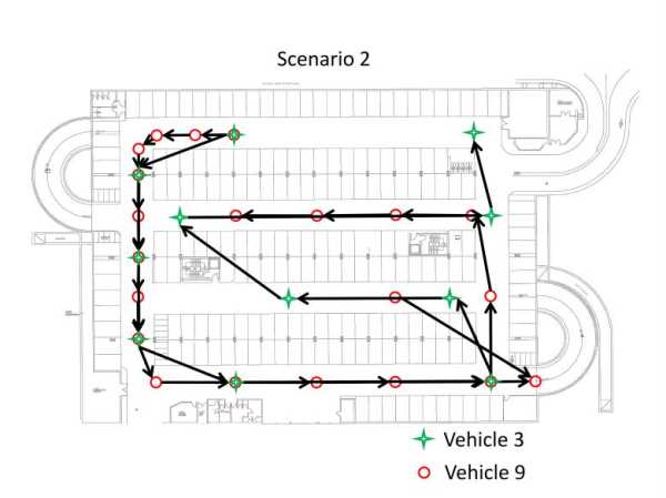
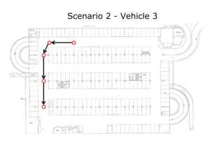
Figure 1: Typical trajectories of two vehicles
recorded using the RFID CoO positioning system. Figure 1 shows the
vehicle trajectories obtained using the RFID CoO technique from two
vehicles traveled at low speeds. Clearly, despite the missing
information at certain sections, vehicle kinematics including average
velocity, inter–vehicle distances and total travelled distance is merely
some of the available information that can be stored for each vehicle.
Obviously, point fix spacing between sequential recordings is limited
and constrained by the inter–tag distances.
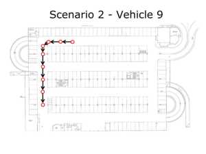
Notwithstanding tag locations were carefully selected at a design stage
to accommodate the nominal tag–reader operation range, data analysis has
indicated that vehicle velocity can impact substantially tag detection.
Figure 2 shows a part of the recorded trajectories for two vehicles
following the same route at different velocities. Evidently, the
navigation solution for a vehicle driving at higher (16 km/h) velocity
(Figure 2, left plot) results in a sparser vehicle trajectory compared
to that obtained for a vehicle driving at a slower (9 km/h) velocity
(Figure 2, right plot) indicating the limitations of the method.
Figure 2: Sections of the trajectories obtained
during the same left turn for vehicles v3 (left) and v9 (left)
5.3 Towards full coverage localization solution based
on Wi–Fi fingerprinting
As shown in the previous section, despite the fact that the RFID
system can serve as a basis for vehicle localization within indoor
parking facilities, user requirements of positioning availability and
coverage depend heavily on tag spatial distribution and density as well
as on vehicle velocity. Today, thanks to the Wi–Fi communication
infrastructure embedded in contemporary smartphones, it becomes possible
to consider such information for assisting the RFID CoO vehicle
navigation solution indoors.
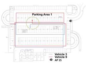
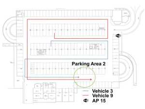
Figure 3 offers a qualitative evaluation of the RSSI values captured
by two smartphones placed on-board the vehicles discussed in the
previous section (LG L5 II and Samsung Galaxy S3 for vehicles v3 and v9
respectively). As shown in the left plot of Figure 3 the two
vehicles enter the parking area from the left, they perform somehow
different routes and park at nearby locations in “parking area 1”.
They remain stationary for a period of about 7 min and then they perform
a second run via different corridors, and finally come to a stop at
“parking area 2” (Figure 3, right plot). The corresponding RSSI
time series received by the Wi–Fi scanner AP15 are presented in Figure
4. In this plot, the stopping times at “parking area 1” and
“parking area 2” refer approximately at ti: 6150 s and tj: 6550 s
respectively. From Figure 4 it is evident that despite the
similarity in the Wi–Fi RSSI time series pattern, the differences in
absolute RSSI values between the two smartphones reveal that Wi–Fi raw
RSSI is unable to provide accurate range measurements.
Interestingly, this also applies for the stationary locations for which
both vehicles were parked at nearby locations.
In fact, the operating environment encountered within indoor garages
affects substantially the stability of the obtained Wi–Fi RSSII values
due to static (e.g. walls, pillars) and dynamic (e.g. vehicles, people)
obstacles that generate shadowing and multipath effects, which by
extension degrade the RF signal propagation. As a result, the
complexity imposed by the continuously varying RF environments does not
allow the establishment of stable RSSII–to–distance models making a real
challenge the use of the lateration positioning technique for Wi–Fi
positioning. Therefore, alternative positioning techniques deemed
necessary, particularly empirical fingerprinting.
Figure 3: Travel trajectories undertaken by for
vehicles v3 and v9S
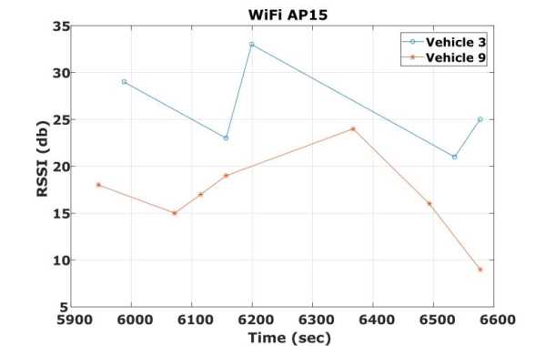
Figure 4: The recorded RSSII values from AP15
during the trajectories of vehicles v3 and v9 The first step in
implementing the fingerprinting technique is the generation of a RSSII
reference map. In order to generate the RSSII training maps, the
RFID–logged positions are associated with the Wi–Fi RSSII values
recorded at the same timestamps. Notably, the Wi–Fi scanning
sessions are detected on average every 2–3 min (see Figure 4) as the
sampling rate of the Wi–Fi scanners depends on the Wi–Fi activations of
each mobile device. Sample trials have indicated that the minimum
time offset observed between the RFID and Wi–Fi time records is of the
order of 3 s. Therefore, the time mismatch between the RFID and
the Wi–Fi sub–systems is compensated by accepting values coinciding
within a ±3 s time limit. Furthermore, considering that the
average vehicle velocity in these trials is of the order of 9 km/h, the
maximum position error for the obtained RSSII values falls within the
step distance between subsequent tag (7.5 m).
Figure 5 shows the RSSI radio maps obtained for the smartphones
placed on–board two vehicles. Clearly, the very limited common
RFID / Wi–Fi data do not allow the generation of a radio map that covers
the entire test area. However, these representation provides
useful insight for the design of future data collection sessions.
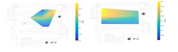
Figure 5: Radio maps generated for the WiFi RSSII
values obtained for the respective RFID positions for vehicle v3
(left) and v9 (right) Examination of Figure 5
in more detail, reveals that despite the sparse RSSI information, the
spatial distribution of RSSI values is somewhat associated with the
characteristics of the indoor environment. This is particularly
evident in the left plot of Figure 5, in which the RSSI radio pattern
follows the actual corridor geometry in the parking lot. Moreover,
the actual RSSI values obtained by the two smartphones seem to be quite
similar; for instance, examine the RSSII values (i.e., 21.5 db versus
22.0 db) obtained by the north–eastern corner of the parking area.
An extension to the previous analysis forms the
implementation of advanced interpolation methods, such as the Voronoi
technique (Gavrilova, 2008), the implementation of which for vehicle v3
leads to Figure 6. Notwithstanding Voronoi technique is not the
ideal approach for interpolating irregularly spaced data, the resulting
radio map describes adequately the RSSII conditions shown in Figure 4.
These findings indicate the potential of Wi–Fi fingerprinting, even for
complex indoor environments. Experimentation with alternative
extrapolating techniques is necessary in order to optimize the training
phase of Wi–Fi fingerprinting.
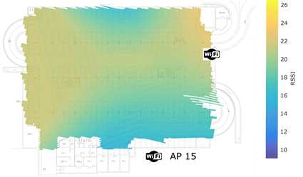
Figure 6: Voronoi polygons based interpolated
radio map generated for vehicle v3 6.
DISCUSSION AND Proposal FOR POSITIONING VEHICLES INDOORS
Based on the analyses and the test results
obtained with the RFID CoO and Wi–Fi systems, a conceptual approach of a
positioning system design is proposed in this section.
6.1 RFID / WiFi localization based on dynamic
fingerprinting map updating
Overly, the proposed positioning system relies on
RFID CoO derived positions and Wi–Fi RSSII maps generated at an
initialization training phase. More specifically, the complete
positioning approach is divided in two parts. The first one
utilizes the RFID CoO technique for obtaining the primary positioning
information, while it engages the Wi–Fi monitoring technique for the
sections lacking RFID positioning. The second part refers to a
dynamic radio map updating concept that continuously compensates for the
temporal RSSII variations usually found in dynamic indoor environments.
Thereby, during the first part, the position solution of a vehicle is
determined relying solely on RFID CoO position fixes. For the occasions
that RFID does not provide a position solution for a certain amount of
time, either due to a lack of RFID tag coverage or missed detection of
tags, the navigation system automatically engages the Wi–Fi
fingerprinting positioning technique. Despite the fact that the
position accuracy provided using the Wi–Fi radio maps is inferior to
the RFID technique, it still enables continuous positioning until a new
RFID position fix becomes available or until the vehicle is identified
being in a “stationary state”.
Figure 7 illustrates the previous example. In
this plot the black dots represent the RFID CoO vehicle positions fixes.
Here, while the vehicle performs a right turn it does not detect any
RFID tag. As a result, soon after, the navigation system engages
the Wi–Fi fingerprinting mode, while it attempts continuously to scan
for new tag detections. Subsequently, the system continues to
perform in this mode until a successful RFID position fix occurs, and
then the positioning responsibility returns back to the RFID system.
Notably, during the stage for which positioning is performed using the
RFID system, the Wi–Fi fingerprinting database is continuously updated
using all information available from the vehicles in the operating area.
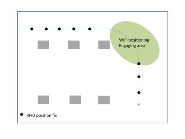
Figure 7: Schematic view of a vehicle employing
the RFID CoO / Wi-Fi fingerprinting algorithm The flow chart of Figure 8 describes the main steps of the proposed
system. Specifically, a mobile vehicle is tracked continuously
using the RFID CoO technique, while at the same time is monitored by the
Wi–Fi scanners that record the respective RSSII values. This
information is processed in near–real time for quality control (outlier
rejection) purposes and the respective information is stored in the
existing radio database. In the case for which RFID positioning
becomes unavailable, vehicle positioning relies solely on Wi–Fi RSSI
using the most recently updated radio map.
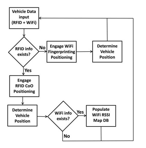
Figure 8: Flowchart of the proposed localization
scheme with the simultaneous dynamic radio map updating At an implementation stage, it is expected that the RSSI Wi–Fi values
can vary considerably between smartphones due to differences found in
antenna manufacturing and due to variable effects in RF signal
propagation as a function of the metallic body of the hosting vehicle.
Experimental testing employing a large amount of data obtained using
different configuration set–ups can provide valuable information for a
better understanding of the environmental effects on the position
solution.
Through storing the long–term information of the dynamic radio database,
further analysis of the RSSII variations it is possible that can help
optimizing the system efficiency while improving positioning accuracy.
Moreover, cross–comparison between the long–term temporal RSSII
variations against the number of vehicles inside a parking facility, it
can reveal a relationship between the vehicle loads within a facility
and the Wi–Fi radio environment. Such knowledge can open the road
for the creation of RSSII prediction models based on external input that
can be integrated into a radio maps development procedure improving the
overall system accuracy and stability.
6.2 Potential for further enhancement
Further improvements to the main idea of the RFID CoO / Wi–Fi system for
vehicle positioning indoors is possible using advanced analyses
techniques and / or heterogeneous sensor data.
Recent developments on Wi–Fi positioning, known as Differential Wi–Fi
(DWi–Fi), have shown promising results on improving the accuracy of the
fingerprinting method using distance corrections (Retscher and Tatschl,
2016a; Retscher and Tatschl, 2016b). In this approach the
path–loss model errors are eliminated by differencing model–derived
distances from the same AP leading to positioning accuracy of the order
of 0.5 m – 1.0 m. Implementing this technique in the proposed
positioning system is expected to improve its performance, provided that
the required infrastructure of additional APs is possible while
simultaneously preserving the cost of the system.
The benefits arising from a low–cost indoor positioning system for
indoor parking facilities management can be further enhanced – while
increasing the overall system accuracy and robustness – if it ecompasses
Ultra Wide Banded (UWB) system thanks to its high accuracy potential and
foreseable decreasing costs. Based on this approach, further improvement
of the proposed system would include the employment of low–cost UWB
transceivers placed at each vehicle.
7. CONCLUDING REMARK
In this study, a new system approach for positioning vehicles within
indoor parking facilities is presented. The system relies on the
use of RFID CoO and Wi–Fi measurements. Particularly, an
algorithmic proposal is introduced to provide continuous vehicle
positioning based on dynamically updated Wi–Fi radio maps, while vehicle
positioning is primarily obtained using the RFID CoO technique.
The performance of both systems is examined using real data obtained
from an extensive field campaign. Analysis reveals the high
potential of the proposed approach in terms of positioning accuracy and
availability, while ideas for further enhancement of the system are
envisioned. Scaling up the system to greater size parking facilities or
even more to an area-wide level would require tackling equipment
availability issues while at the same time database creation and
maintenance should be carefully planned.
8. ACKNOWLEGEMENTS
This research was supported by the Action: ARISTEIA-II (Action’s
Beneficiary: General Secretariat for Research and Technology),
co-financed by the European Union (European Social Fund –ESF) and Greek
national funds.
9. REFERENCES
- Alam, K.M.; Saini, M.; El Saddik, A.E., 2015, Workload Model Based
Dynamic Adaptation of Social Internet of Vehicles. Sensors, 15,
23262–23285.
- Antoniou, C., Balakrishna, R., Koutsopoulos, H.N., Ben-Akiva M., 2011,
Calibration methods for simulation-based dynamic traffic assignment
systems, Int. Journal of Modeling and Simulation, Vol. 31, No. 3, pp.
227-233
- Antoniou, C., Gikas, V., Papathanasopoulou, V., Mpimis, T., Perakis, H.,
Kyriazis, C., 2017, A framework for efficient data collection and
modeling of indoor parking facilities under constraints, 96th
Transportation Research Board, January 8 – 12, Washington DC
- Baum, M., 2011, RTL in Longueuil selects bus yard management solution
provided by Solotech, ISR Transit and Ubisense,
Available online:
http://www.ubisense.net/en/news–and–events/press–releases/rtl–in–longueuil–selects–bus–yard.html
(accessed on 1 September 2014)
- Bojja, J., Kirkko-Jaakkola, M., Collin, J., Takala, J., 2013, Indoor 3D
navigation and positioning of vehicles in multi-storey parking garages,
International Conference on Acoustics, Speech and Signal Processing
(ICASSP), pp. 2548-2552, IEEE, May 26-31 Vancouver
- Gavrilova, M., 2008, Generalized Voronoi Diagram: A Geometry-Based
Approach to Computational Intelligence, p 312, Springer-Verlag Berlin
Heidelberg
- ikas, V., Retscher, G., 2015. An RFID-based virtual gates concept as a
complementary tool for indoor vehicle localization, Int. Conf. on Indoor
Positioning and Indoor Navigation (IPIN), October 13-16, Banff, Alberta
- Gikas V., Antoniou C., Retscher G., Panagopoulos A., Perakis H., Kealy
A., Mpimis A., Economopoulos T., Marousis A., 2015, A Low-cost RFID/WiFi
Positioning Solution for Parking Facilities Management, 9th Int. Symp.
on Mobile Mapping Technology, Dec. 09–11, Sydney, Australia
- Gikas, V., Antoniou, C., Retscher, G., Panagopoulos, A., Kealy, A.,
Perakis, H., Mpimis, T., 2016a, A low-cost wireless sensors positioning
solution for indoor parking facilities management, Journal of Location
Based Services, pp. 1-21
- Gikas, V., Retscher, G., Ettlinger, A., Perakis, H., Dimitratos, A.,
2016b, Full-scale Testing and Performance Evaluation of an Active RFID
System for Positioning and Personal Mobility, Int. Conf. on Indoor
Positioning and Indoor Navigation (IPIN), October 4-6, Alcalá de
Henares, Spain
- Ibisch, A., Stumper, S., Altinger, H., Neuhausen, M., Tschentscher, M.,
Schlipsing, M., Knoll, A., 2013, Towards autonomous driving in a parking
garage: Vehicle localization and tracking using environment-embedded
lidar sensors, IV Intelligent Vehicles Symposium, pp. 829-834, June
23-26, Australia, IEEE
- Kladeftiras, M., Antoniou C., 2013, Simulation-based assessment of
double-parking impacts on traffic and environmental conditions,
Transportation Research Record: Journal of the Transportation Research
Board, Vol. 2390, pp.121-130
- Kümmerle, R., Hähnel, D., Dolgov, D., Thrun, S., Burgard, W., 2009,
Autonomous driving in a multi-level parking structure, International
Conference on Robotics and Automation (ICRA ‘09), pp. 3395-3400, May
12-17, Kobe Japan, IEEE
- Mautz, R., 2012, Indoor Positioning Technologies, Habilitation Thesis, p
127, ETH Zurich Switzerland
- Retscher, G., Tatschl, T., 2016a, Differential Wi-Fi – A novel approach
for Wi-Fi Positioning Using lateration, FIG Working Week, May 2 – 6,
Christchurch, New Zealand
- Retscher, G. Tatschl, T., 2016b, Indoor Positioning Using Wi-Fi
Lateration – Comparison of two Common Range Conversion Models with Two
Novel Differential Approaches, IEEE Xplore, 2016 Ubiquitous Positioning
Indoor Navigation and Location Based Service (UPINLBS), November 3–4,
Shanghai, PR China
- Shuaib, A., Salman, A., Saddam, H., Ejaz, H., 2015, 3-Dimensional Indoor
Positioning System based on WI-FI Received Signal Strength using Greedy
Algorithm and Parallel Resilient Propagation, International Journal of
Computer Applications, Vol 116 – No. 18, pp. 32-38
- WLAN Positioning Technology 2014, White Paper, Issue 1.0, Date
2014-04-24, Huawei Technologies Co., Ltd.
BIOGRAPHICAL NOTES
Vassilis Gikas received the Dipl. lng. in Surveying Engineering from the
National Technical University of Athens (NTUA), Greece and the Ph.D.
degree in Kalman filtering and Geodesy from the University of Newcastle
upon Tyne, UK, in 1992 and 1996, respectively. He is currently an
Associate Professor with the School of Rural and Surveying Engineering,
NTUA. ln the past (1996-2001) he served the offshore and land
seismic industry in the UK and the USA as a navigation and positioning
specialist and more recently (2001-2005) he served the private sector in
a series of surveying and transportation engineering projects under the
same capacity. His principal areas of research include sensor fusion and
Kalman filtering for navigation and mobile mapping applications as well
as engineering surveying and structural deformation monitoring and
analysis.
Harris Perakis is a PhD candidate at School of Rural and Surveying
Engineering of the National Technical University of Athens. He holds a
Dipl. lng. in Surveying Engineering from the same School (2013). His
scientific interests include positioning within indoor and hybrid
environments, trajectory assessment and geodetic sensor data fusion.
Allison Kealy is an Associate Professor in the University of Melbourne
and as been a researcher in sensor fusion and satellite positioning
systems for almost two decades. Her research interests are in sensor
fusion, Kalman filtering, GNSS quality control, with application in
wireless sensor networks and location-based services.
Guenther Retscher is an Associate Professor at the Department of Geodesy
and Geoinformation of the Vienna University of Technology, Austria. He
received his Venia Docendi in the field of Applied Geodesy from the same
university in 2009 and his Ph.D. in 1995. His main research and teaching
interests are in the fields of engineering geodesy,satellite positioning
and navigation, indoor and pedestrian positioning as well as application
of multi-sensor systems in geodesy and navigation.
Thanassis Mpimis is a PhD student at the National Technical University
of Athens (NTUA). He holds a degree in IndustriaL Management & Technology
from University of Pireaus (2004), the Dipl. Ing. Degree in Surveying
Engineering from NTUA (2009), and the MSc in Techno-Economical from NTUA
(2007). His principal areas of interest include sensor fusion for land
and sea navigation applications and deformation monitoring of structures
with emphasis on GNSS and ground-based interferometry.
Constantinos Antoniou is a Full Professor in the Chair of Transportation
Systems Engineering at the Technical University of Munich (TUM),
Germany. He holds a Diploma in Civil Engineering from NTUA (1995), a MS
in Transportation (1997) and a PhD in Transportation Systems (2004),
both from MIT. His research focuses on modelling and simulation of
transportation systems, Intelligent Transport Systems (ITS), calibration
and optimization applications, road safety and sustainable transport
systems. He has authored more than 250 scientific publications,
including more than 70 papers in international, peer-reviewed journals,
170 in international conference proceedings, a book and 17 book
chapters.
CONTACTS
Dr. Vassilis Gikas
National Technical University of Athens
Department of Rural and Surveying Engineering
Laboratory of General Geodesy
9 Heroon Polytechniou Str., 15780, Zographou, Athens
GREECE
Tel. +30 210 772 3566
Fax. +30 210 772 2728
Email: vgikas@central.ntua.gr
|